Digitising contacts and structures: drawing, GPS and geometry editing
Freehand stylus drawing over imagery, GPS-traced geometries, magnetic snap, and union, intersection and DEM-intersection operations.
Digitising contacts and structures: drawing, GPS and geometry editing
Map
This control presents two main contexts, each with specific tools:
- Viewing context: Lets you search and explore georeferenced data.
- Editing context: Activated when modifying a geometry, showing specific tools.
Both share the following elements:
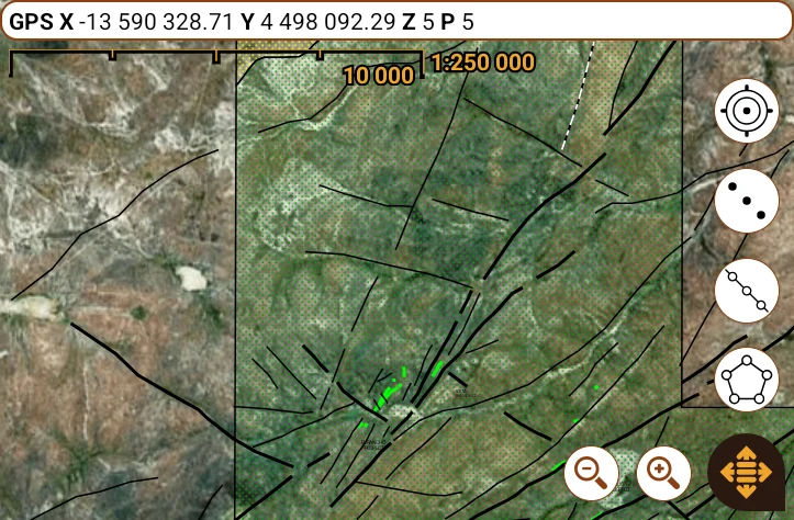
- Status bar: Shows the current XYZ position according to the selected GNSS device (see Preferences Window), in the chosen coordinate system. It also indicates the precision in meters (after the letter “P”). Tapping it deselects the active geometry or tuple, the same as tapping an empty area of the map.

 Scale: Includes a reference ruler with its length in the defined system. On the right, the actual scale is shown, which depends on the device's screen density. It is recommended that the user verify this value on their device.
- Main button: (see Main Button).
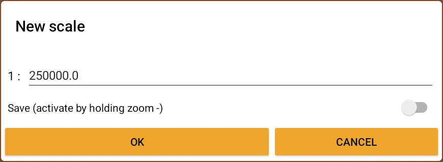
- Zoom control: Buttons to zoom the map in or out. By holding down Zoom + you can enter a specific scale and save it; then you can recall it by holding down Zoom -.

- Map gestures: You can drag with a finger or stylus to navigate. You can also enable automatic tracking of the GNSS location (see Preferences Window). To change the scale, use the two-finger “pinch” gesture.
Tools in Viewing Context
 Geocode the current position: Creates a point with the current GNSS coordinates and saves it in the selected table (see Vector Layers). Then, the geocoder assistant opens(see Geocoders). The first time it is used in a table, you will be asked to define the default style (see Styles).
 Draw and geocode geometry: Switches to the editing context to draw a multipoint, a polyline, or a polygon. Then, the geocoder assistant opens. Here too, on first use, you will be asked to set the default style.
- Quick access buttons: Represents layers into which a geometry type can be entered with a single tap. They are configured in the layer menu or by holding it down. (see Vector Layers).
Additionally, in this context, you can tap any geometry of a touchable layer on the map to select it (see Layer Menu). When doing so, the geometry will be selected and a menu with options identical to the one in the data browser will open (see Data Browser).
If instead you hold your finger (or stylus) down on the geometry (long touch), instead of the menu you go straight into the node editor, as long as the geometry has editable georeferencing (the same condition that enables "Edit geometry" in the menu); if not, only the menu opens.
Geometry Editor (Editing Context)
The map's editing context is activated when editing a georeferenced geometry or using the measurement tool. It includes specific editing tools and, in the status bar, shows both the GNSS device information and the general spatial information of the geometry and the selected node:
- NOD X, Y and Z: Coordinates of the selected node in the map's unit of measurement. In tables that only support XY, the Z is not shown.
- AZ, DP, D and Dz: Azimuth, dip, and length of the vector between the previous node and the currently selected node. If the coordinate has a Z component, Dz is the three-dimensional length of the vector, and D is the flattened length (ignoring the z values)
- TD and TDz: Total length of the polyline. If the coordinate has a Z component, TDz is the three-dimensional length of the polyline, and TD is the flattened length (ignoring the z values)
- TP: Total perimeter of the polygon, ignoring the Z component of its nodes if they have one.
- TA: Total area of the polygon, also ignoring the Z component.
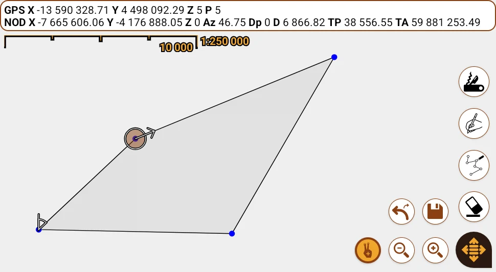
The figure being edited can be hidden or shown using the  button in the layer menu. And on the map, it is represented as follows:
 Common nodes of lines and polygons.
 Selected node: Indicates with an arrow the direction of the next vector.
 Node before the selected one: Shows the azimuth toward the next node. The numeric value is displayed in the status bar.
 Normal and selected nodes in points and multipoints.
The controls available in this context are:
 Pan: Toggles between moving the map with touch gestures (drag/pinch) or using the active tool. This button is not shown if stylus support is enabled (see Preferences Window), since in that case finger gestures are used for navigation and the EMR stylus for editing.
 Undo/redo: Lets you revert the last action by tapping it, with a confirmation sound. If held down, it redoes the last reverted action repeatedly. If there are no actions to undo, you will be asked to confirm exiting the editing mode.
 Save and exit: Saves the changes and closes the editor. If it is a new geometry, the geocoder will open to enter the attributes of the target table. The edit can be reverted by tapping the undo/redo button in the layer menu.
 Remove nodes: When activated, it removes nodes when you tap them or drag the pen over them.
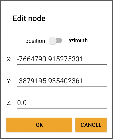
 Edit node: Lets you drag a node to a new position. When tapping a selected node, a window opens to modify its coordinates or reference its position relative to the previous node. If you tap this tool's icon while it is already active, an option opens to add a new node after the selected one. Holding down the button enables or disables the snap function (magnetic nodes).
 Freehand drawing: When activated, it lets you draw freely from the selected node. You can enter nodes by tapping the map one by one or by dragging the pen, with a distance between nodes defined in the “Drawing node interval” field (see Preferences Window). If you tap the button again, the active node is deselected, which lets you start a new figure (in lines and polygons).
Snap (magnetic nodes):
This function helps automatically align nodes with other existing ones in the same or another layer. To do so, you must select in the layer menu which ones will have this property (see Layer Menu).
There are two types of snapping:
- Proximity snap (active by default): Automatically aligns nodes if the pen is close enough.
- Absolute snap (enabled from preferences): Only allows placing nodes on top of already existing ones (magnetic nodes), with no option to draw freely.
It can be temporarily enabled or disabled by holding down the node editing button  .
.
Extra Tools:
Accessible from the button with the Swiss army knife icon  . It includes:
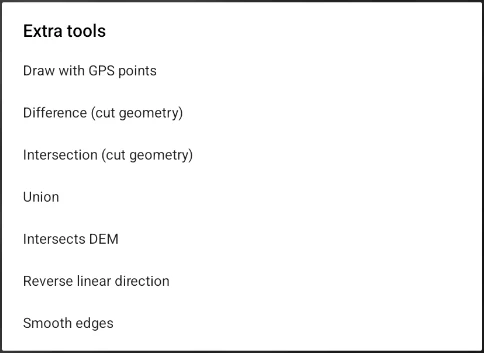
- Draw with GPS points: Uses the GPS to trace geometries instead of the pen. Useful for recording elements such as veins or outcrops. The distance between nodes can be configured in preferences (see Preferences Window). Capture continues even if the screen turns off: while it runs, Android shows the "Capturing GPS nodes (N)" notification, with the number of nodes taken and a Stop button, which ends the capture and leaves the geometry ready to keep editing. If a track is also being recorded, there is a single notification, "Saving tracks · capturing GPS nodes (N)", with the Stop track and Stop capture buttons.
- Difference (cut geometry): Applies a difference operation with other geometries. Just tap the desired geometries, as long as they belong to a touchable layer (see Layer Menu).
Note: You can enable the “Auto-Repair Geometries Before Operation” option in the Preferences Window to avoid errors.
- Intersection (cut geometry): Similar to the previous one, but applies the intersection operation.
- Union: Applies a union operation with other geometries.
- Reverse linear direction: Changes the direction of lines or polygons, useful for modifying styles, references, or the direction of roads.
- Smooth edges: Sequentially analyzes the angles between nodes and removes those that generate angles outside a defined range. When activated, it lets you configure the limit values in a pop-up window.
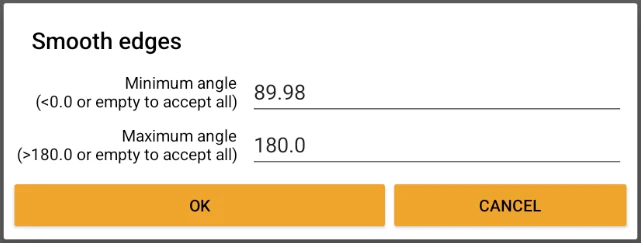
Note: It is also possible to enable “Auto-Smooth Geometries After Operation” in the Preferences Window to apply automatic smoothing after operating between geometries. This is useful if you notice “spikes” (very sharp angles) in the results.
- Intersect DEM (Only when editing lines): Draws a polyline resulting from the intersection between a plane and a DEM. When you activate this tool, you can tap a point geometry or any position on the map.
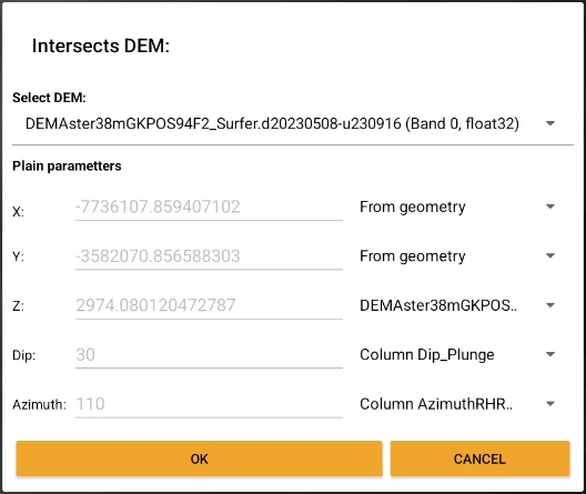
After choosing the position, a dialog will open where you can select a source DEM within the project (it does not need to be loaded as a layer) and define the parameters of the intersecting plane.
The parameters are: X, Y, Z, Dip, and Azimuth. To the right of each value there is a spinner that lets you choose different sources: the position tapped on the screen, the selected point, a value from one of its columns (if you tapped on one), or, in the last three cases, a value derived from the X/Y position of a DEM present in the project. You can also assign a custom value by selecting that option in the spinner and typing it in the corresponding text box.
When you accept, the intersection process begins, which can be canceled at any time by pressing Back. Once finished, the resulting polyline is added to the cosmetic layer.
As an alternative, you can generate quick intersections by tapping directly on a point of the map in viewing mode (see Context menu options in Data Browser).
You've read enough. Try it with your own project.
20 days free, with your data. If you get stuck: the manual — and us.
Secure payment with Stripe · Cancel anytime.